Using Relays in Automotive Wiring
Relays are a mechanical device that can connect or disconnect power to an accessory when it gets a low voltage ‘signal’ from a switch. Some people may ask why they should bother using a relay when you can just wire an accessory directly through a switch to its power source. There are two main reasons why relays are utilised:
Using a relay keeps the higher voltage out of the passenger compartment of the vehicle and is just less taxing on your vehicle’s electrical system in general. If something were to fail and short, the chances of an interior fire are significantly reduced if a relay is utilized to allow the higher voltage switching occur in the engine compartment. This also reduces the load on the interior fuse panel by placing a smaller demand on it.
It allows the use of less heavy gauge wire. The longer the wire, the higher the resistance. By using a relay near the item being switched, you use less of the heavier gauge wire.
Some may argue that relays add an additional failure point to an electrical system. Although relays do eventually wear out after repeated use, the potential for failure can be reduced if they are replaced periodically, or you could wire two relays in parallel. If wired in parallel, one relay can fail and the other can continue to operate. This technique is commonly used in cooling fans.
Consider a typical user upgrade – adding fog lamps to the front of a vehicle. Many would tap into power at the fuse block, run it to a dash mounted switch, then back through the firewall all the way forward to the lights. Wiring with a relay allows the power to run straight from the battery, through the relay mounted nearby, directly to the lights. The interior mounted switch only draws minimal power though the interior fuse block to activate the relay.
Let's look at a simple schematic that uses a relay to power up a fog light bar:
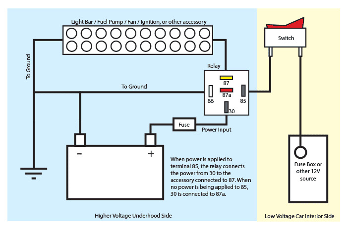
Positive power from the battery would not only run from the battery to the relay block, but also to other areas such as a fuse block on the vehicle. In the above drawing, the Fuse Box on the right would be receiving 12 volt supply from the battery.
When the switch is turned on power goes to pin 85, which energises a coil that creates an electro-magnetic field. It is able to energise the coil as the other side of the coil is attached to Pin 86 which completes the circuit to the negative or "ground" on the battery. This electromagnetic field, like any other magnet, pulls the metal contactor closed and completes the circuit between pin 30 and pin 87 to allow power to now run from the positive terminal, through the fuse and up to the light bar.
The picture below shows a typical automotive style 5 pin relay
The picture below shows the schematic for the 5 pin relay relay.
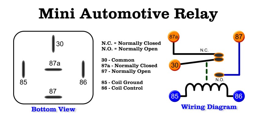
Relays come in many varieties. The one above is a 5 pin relay. The simplest relay would be a 4 pin relay. The 4 pin relay would have 2 low amperage pins to connect the coil to a switch and another 2 pins for the high amperage circuit to close and connect power to a module. The advantage of the 5 pin relay is the choice of having a normally open (N.O.) circuit or a (N.C.) circuit.
A N.O. circuit means that the contactor inside the relay is "Normally open" so voltage is NOT able to flow through the relay and the module being powered up would be effectively turned off if no power is energising the coil.
A N.C. circuit means that the contactor inside the relay is "Normally closed" so voltage IS able to flow and the module being powered up would be effectively turned on all the time if no power is energising the coil. When the switch is turned on the coil becomes energised inside the relay and cuts the power off to the module, turning it off.
An advantage to the 5 pin relay is you can alternate between two modules.